
6-35kV Oil-Immersed Transformer
Categories:
Oil-lmmersed Power Transformer
Email:info@byttransformers.com
Product Pictures


6-35kV Oil-immersed Power Transformer
Overview
Our 6-35kV oil-immersed power transformer series is designed for reliable, efficient power distribution in utility, industrial, and renewable energy applications. Covering a wide voltage range from 6kV up to 35kV, these transformers are fully customizable to meet your specific project requirements – whether you need a standard distribution unit or a special impedance/rectifier design.
Key Features
Wide voltage coverage – Available in voltage classes: 6kV, 10kV, 11kV, 13.2kV, 13.8kV, 15kV, 20kV, 22kV, 24kV, 30kV, 33kV, and 35kV.
Customizable capacity – From 30kVA up to 20,000kVA (20MVA).
Loss levels – Standard, medium, low, and ultra‑low losses (meeting or exceeding IEC 60076 and EU Eco Design Tier 2 requirements). Ultra‑low loss units can adopt amorphous alloy cores.
Tap changers – Off‑circuit (NLTC) or on‑load (OLTC), providing precise voltage regulation.
Cooling methods – ONAN (natural) or ONAF (forced air), adaptable to site conditions.
Robust construction – Conservator or hermetically sealed tanks with fin‑type radiators, suitable for outdoor installation in harsh environments (ambient temperature from -40°C to +55°C, altitude up to 4000m).
Standards compliance – Designed and tested according to IEC 60076, with optional compliance to GB, NBR, or other national standards.
Quality Assurance
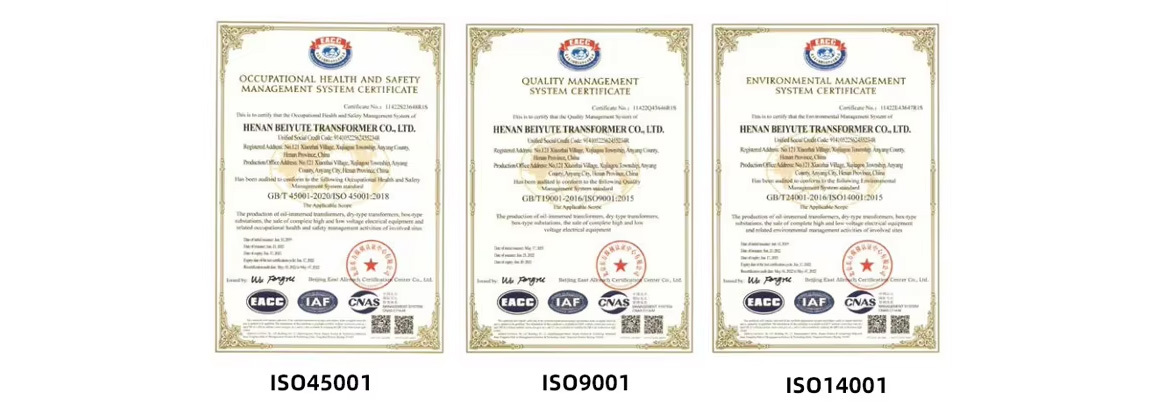
Every transformer undergoes routine tests in our own laboratory. We also offer witness tests and can arrange third‑party inspection at accredited laboratories upon request. Our factory holds ISO 9001, ISO 14001, and CE certifications.
Typical Applications
Power distribution – Substations, rural grids, industrial parks, commercial complexes (with transformer installed outdoors or in dedicated fire‑proof transformer rooms).
Renewable energy – Solar and wind power plants requiring medium‑voltage step‑up (e.g., 0.4/6‑35kV).
Industrial – Mines, cement plants, oil & gas facilities, and other heavy industries where oil‑immersed transformers are permitted.
Infrastructure – Railways, ports, pumping stations, and irrigation projects.
⚠️ Important note
Oil‑immersed transformers contain mineral oil. For indoor installations in high‑rise buildings, subways, airports, or other densely populated spaces, please refer to our dry‑type transformer series .
Why Choose KAIBEITE?
15+ years of manufacturing experience.
Full customization – Voltage, capacity, loss level, winding material, accessories.
Global track record – Exported to more than 20 countries including Ethiopia, Tanzania, Russia, Brazil, and the Philippines.
Fast delivery – Standard lead time 15‑30 working days after order confirmation.
Responsive support – Technical assistance, installation guidance, and warranty service.
Technical Parameters (example)
Parameter Value Range
Rated power 30 – 2500 kVA (distribution); up to 20000 kVA (OLTC)
HV voltage 6 – 35 kV
LV voltage 0.2 – 1.1 kV (customizable)
Vector group Dyn11, Yyn0, YNd11, etc.
Tapping range ±2×2.5% (NLTC) or ±8×1.25% (OLTC)
Insulation level HV: 45/60/70/85/95 kV (lightning impulse 105/125/170/200 kV)
No‑load loss IEC standard or better
Load loss IEC standard or better
30-2500KVA 6-11KV Oil-Immersed Transformer | ||||||||
Rated Capacity | Voltage Combination | Vector Group | No-Load Loss(w) | Load Loss | No-Load Current (%) | Short Circuit Impedance (%) | ||
High Voltage(kV) | Tapping Range | Low Voltage (kV) | ||||||
30 |
6-11 |
±5% ±2×2.5% |
0.4 |
Dyn/Ynd Yzn/Yyn | 100 | 630 | 2.0 |
4 |
50 | 130 | 910 | 2.0 | |||||
63 | 150 | 1090 | 1.9 | |||||
80 | 180 | 1310 | 1.5 | |||||
100 | 200 | 1580 | 1.5 | |||||
125 | 240 | 1890 | 1.3 | |||||
160 | 280 | 2310 | 1.3 | |||||
200 | 340 | 2730 | 1.1 | |||||
250 | 400 | 3200 | 1.1 | |||||
315 | 480 | 3830 | 1.0 | |||||
400 | 570 | 4520 | 1.0 | |||||
500 | 680 | 5410 | 1.0 | |||||
630 | 810 | 6200 | 0.9 |
4.5 | ||||
800 | 980 | 7500 | 0.85 | |||||
1000 | 1150 | 10300 | 0.85 | |||||
1250 | 1360 | 12000 | 0.85 | |||||
1600 | 1640 | 14500 | 0.85 | |||||
2000 | 1940 | 19500 | 0.7 | 5 | ||||
2500 | 2290 | 21200 | 0.7 | 5 | ||||
30-2500KVA 20KV Oil-immersed transformer | ||||||||
Rated Capacity | Voltage Combination | Vector Group | No-Load Loss(w) | Load Loss | No-Load Current (%) | Short Circuit Impedance (%) | ||
High Voltage(kV) | Tapping Range | Low Voltage (kV) | ||||||
30 |
20-24 |
±5% ±2×2.5% |
0.4 |
Dyn/Ynd Yzn/Yyn | 90 | 690 | 2.1 |
5.5 |
50 | 130 | 1010 | 2 | |||||
63 | 150 | 1200 | 1.9 | |||||
80 | 180 | 1440 | 1.8 | |||||
100 | 200 | 1730 | 1.6 | |||||
125 | 240 | 2080 | 1.5 | |||||
160 | 290 | 2540 | 1.4 | |||||
200 | 340 | 3000 | 1.3 | |||||
250 | 400 | 3520 | 1.2 | |||||
315 | 480 | 4210 | 1.1 | |||||
400 | 570 | 4970 | 1 | |||||
500 | 680 | 5940 | 1 | |||||
630 | 810 | 6820 | 0.9 |
6 | ||||
800 | 980 | 8250 | 0.8 | |||||
1000 | 1150 | 11330 | 0.7 | |||||
1250 | 1380 | 13200 | 0.7 | |||||
1600 | 1660 | 15950 | 0.6 | |||||
2000 | 1950 | 19140 | 0.6 | |||||
2500 | 2340 | 22200 | 0.5 | |||||
50-2500KVA 33-38.5KV Oil-Immersed Transformer | ||||||||
Rated Capacity | Voltage Combination | Vector Group | No-Load Loss(w) | Load Loss | No-Load Current (%) | Short Circuit Impedance (%) | ||
High Voltage(kV) | Tapping Range | Low Voltage (kV) | ||||||
50 |
30-38.5 |
±5% ±2×2.5% |
0.4 |
Dyn/Ynd Yzn/Yyn | 170 | 1200 | 2.1 |
6.5 |
100 | 230 | 2010 | 2.0 | |||||
125 | 270 | 2370 | 1.5 | |||||
160 | 290 | 2820 | 1.4 | |||||
200 | 340 | 3320 | 1.3 | |||||
250 | 400 | 3950 | 1.2 | |||||
315 | 480 | 4750 | 1.1 | |||||
400 | 580 | 5740 | 1.0 | |||||
500 | 680 | 6910 | 1.0 | |||||
630 | 830 | 7860 | 0.9 | |||||
800 | 980 | 9400 | 0.8 | |||||
1000 | 1150 | 11500 | 0.7 | |||||
1250 | 1400 | 13900 | 0.6 | |||||
1600 | 1690 | 16600 | 0.6 | |||||
2000 | 1990 | 19700 | 0.6 | |||||
2500 | 2360 | 23200 | 0.6 | |||||
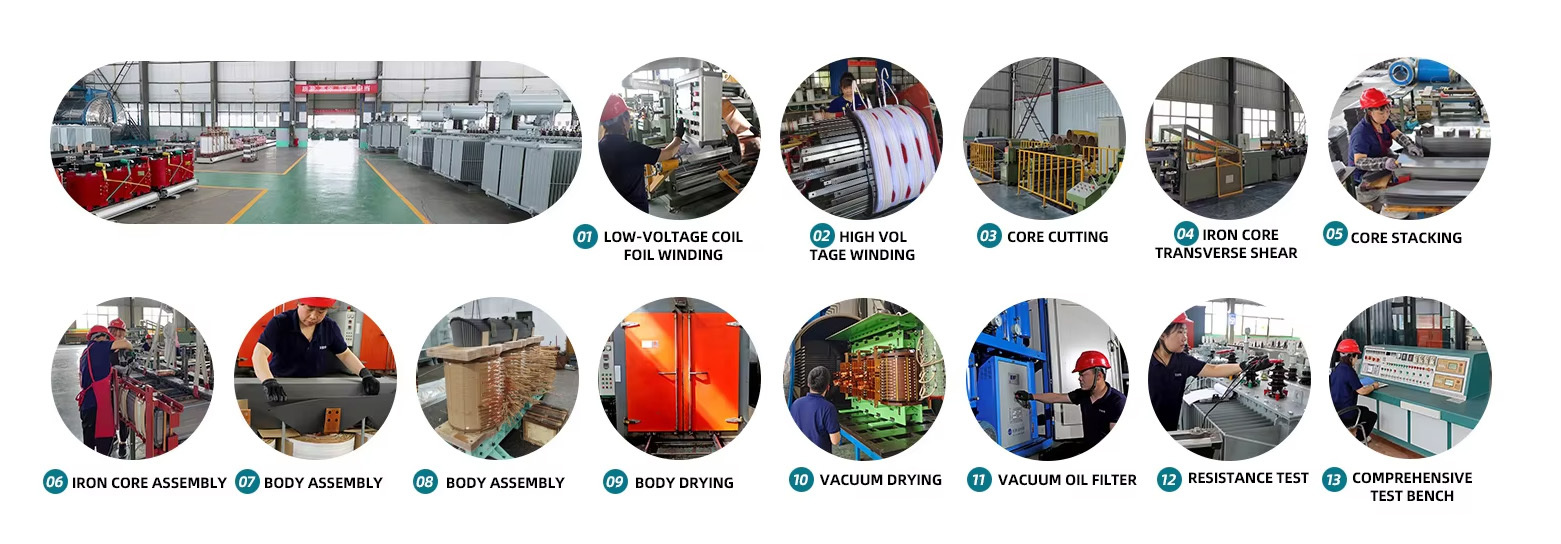
Production proces
Customer Case

Cooperation Partners

Our Exhibition

Our Certificates
Payment & Delvery

FAQ
Q1.Do you have MOQ?
Q2.Should the customer pay the delivery fee,How much is it?
For the delivery fee, many samples are be requested to be sent,so we must get delivery fee. If you tell me to use the appointed Express, you will give me your express account or you will pay according to the Express.
Q3.How about the after sale service?
Q4.When can I get a price?
Q5: Are you a trade company or manufacturer?
Key words:
Oil Immersed Transformer
6kV
10KV
11KV
22KV
3000kVA/33/400V
35KV
oil-immersed transformer")


Leave a message
Leave your contact information and we will contact you during business hours


Phone/WhatsApp:
Email:
Address
Kaibeite Industrial Park, No. 121 Xiaozhai Town, Anyang, Henan Province, China
HUATAO GROUP
Leave Message
Expand your business with a trusted partner