
Transformer structure and the function of each component summary
The transformer is mainly composed of iron core, winding, oil tank, oil pillow and insulating bushing, tap changer and gas relay, etc., and the functions of each part are as follows.
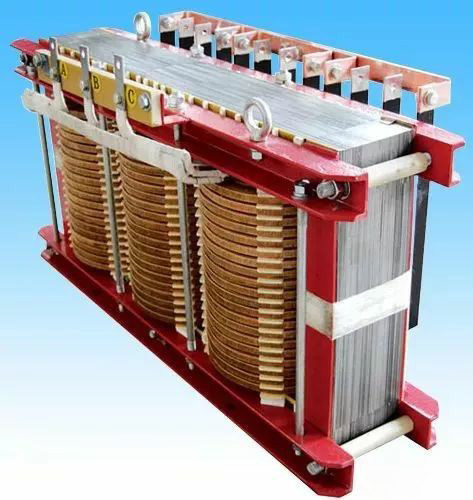
Iron core
The core is the part of the magnetic circuit of the transformer; In order to reduce the hysteresis and eddy current losses of the iron core under the action of alternating magnetic flux, the iron core is made of high-quality silicon steel sheets with a thickness of 0.35mm or less. At present, the factory widely uses cold-rolled grains with high permeability to replace silicon steel sheets, so as to reduce the volume and weight, and also save the wire and reduce the heat loss caused by the wire resistance.
The iron core consists of two parts: the iron core column and the iron yoke. The core column is wounded, and the iron yoke connects the core column to form a closed magnetic circuit. According to the arrangement of the windings in the core, transformers are divided into two types: core type and iron shell type (or referred to as core type and shell type).
Single-phase two-iron core column. This type of transformer has two core pillars, which are connected by two iron yokes, the upper and lower iron yokes, to form a closed magnetic circuit. Both core pillars are sleeved with high-voltage windings and low-voltage windings. Typically, the low-voltage winding is placed on the inside, i.e. near the core, and the high-voltage winding is placed on the outside, which makes it easier to comply with the insulation class requirements.
There are two types of iron-core three-phase transformers: three-phase three-iron core column type and three-phase five-iron core column type. Three-phase five-iron core column type (or three-phase five-column type) is also known as three-phase three-iron core column side yoke type, which is composed of two side yokes (iron core without winding) on the outside of the three-phase three-iron core column (or three-phase three-column type), but the cross-section and height of the upper and lower iron yokes are smaller than those of ordinary three-phase three-column type. This reduces the height of the entire transformer.
The three-phase three-iron core column is to put the three windings of the three-phase on the three iron core columns respectively, and the three iron core columns are also connected by the upper and lower two iron yokes to form a closed magnetic circuit. The windings are arranged in the same way as single-phase transformers. Three-phase five-iron core column, compared with three-phase iron core, there are two more branch iron core columns on the left and right sides of the iron core column, which becomes a side choke. The windings of each voltage level are respectively set on the middle three core columns according to the phase, and the side yoke has no windings, so that a three-phase five-iron core column transformer is constituted.
Since the magnetic flux of each phase of the three-phase five-column core can be closed by the side yoke, the three-phase magnetic circuit can be regarded as independent of each other, unlike the ordinary three-phase three-column transformer. Therefore, when there is an asymmetric load, the zero-sequence magnetic flux generated by the zero-sequence current of each phase can be closed by the side yoke, so the zero-sequence excitation impedance is equal to the excitation impedance (positive sequence) during symmetrical operation.
Three-phase transformers with medium and small capacities are three-phase three-column type. Large capacity three-phase transformer. It is often limited by the transportation height, and the three-phase five-column type is mostly used.
An iron-shell single-phase transformer has a central core column and two branch core posts (also known as side yokes), and the width of the central core column is the sum of the widths of the two branch core columns. All the windings are placed on the central core column, and the two branch core columns are like "shells" around the outside of the windings, so they are called shell transformers. It is also sometimes referred to as a single-phase three-column transformer.
The core of an iron-shell three-phase transformer can be seen as consisting of three independent single-phase shell transformers arranged side by side.
The structure of the core transformer is relatively simple, the distance between the high-voltage winding and the iron core is far, and the insulation is easy to handle. The structure of the shell transformer is relatively strong, the manufacturing process is more complex, the distance between the high-voltage winding and the core column is closer, and the insulation treatment is more difficult. The shell structure is easy to strengthen the mechanical support of the winding, so that it can withstand large electromagnetic forces, especially suitable for transformers passing through large currents. Shell structures are also used in high-capacity power transformers.
In large-capacity transformers, in order to make the heat emitted by the core loss be fully carried away by the insulating oil during circulation, so as to achieve a good cooling effect, a cooling oil channel is usually provided in the core. The orientation of the cooling oil channel can be made parallel or perpendicular to the plane of the silicon steel sheet.
winding
The arrangement of the windings on the core
The windings of a transformer, according to the arrangement of its high-voltage windings and low-voltage windings on the core, have two basic forms: concentric and overlapping. Concentric, high-pressure and low-voltage windings are all made cylindrical, but the diameter of the cylinder is different, and then coaxial on the core column. The overlapping winding, also known as the cake winding, is divided into a number of wire cakes for its high-voltage winding and low-voltage winding, which are staggered along the height of the core column. Overlapping windings are mostly used in shell transformers.
Core transformers generally use concentric windings. Usually the low-voltage winding is assembled close to the iron core, and the high-voltage winding is sleeved outside the low-voltage winding, and there is a certain insulation gap and heat dissipation oil channel between the low-voltage winding and the high-voltage winding and between the low-voltage winding and the iron core, and is separated by an insulating paper tube.
According to the winding characteristics, concentric windings can be divided into several types, such as cylindrical type, spiral type, continuous type and tangled type.
>>>>
Cylindrical windings
Cylindrical winding is the simplest kind of winding, which is continuously wound with insulated wire along the height of the iron core, after winding the first layer. The pad is interlayer insulating paper and then wound the second layer. This type of winding is generally used for low-voltage windings of small-capacity transformers.
>>>>
Spiral windings
The above-mentioned cylindrical winding is actually also spiral, but the spiral winding mentioned here, the number of wires connected in parallel per turn is more, and it is arranged in parallel along the radial direction by a plurality of insulated flat wires (one pressing one), and then wound along the axial height of the core column like a thread one turn after another, and one turn is like a wire reel.
Spiral windingWhen there are too many parallel wires, the parallel wires are divided into two rows and wound into a double spiral winding. In order to reduce additional losses in the wires, the parallel wires are transposed when winding the spiral windings. This kind of winding is generally a three-phase high-current winding with a capacity of 800kVA and a voltage of less than 35kV.
>>>>
Continuous windings
The continuous winding is composed of a number of wire reels (also known as wire cakes) continuously wound with flat wires, and the connection between adjacent wire reels is alternately on the inner and outer sides of the winding, all of which are naturally connected by the wires of the winding winding, without any joints. This kind of winding has a large application range, and is generally used for windings with a three-phase capacity of more than 630kVA and a voltage of 3~110kV.
>>>>
Tangled windings
The shape of the tangled winding is similar to that of the continuous type, the main difference is that the electrically adjacent turns in each reel of the continuous winding are arranged sequentially, while another turn in the winding is inserted between the electrically adjacent turns of the tangled winding, so that the potential difference between the actual adjacent turns increases. There are many tangled winding welding heads, and winding is time-consuming. The purpose of using the tangled winding is to increase the longitudinal capacitance of the winding, so that in the event of overvoltage, the starting voltage is more evenly distributed between the line turns. Entanglement windings are generally used for high-voltage windings with voltages above 110kV.
The winding is the main heating component of the transformer during operation, in order to make the winding effectively dissipate heat, in addition to the longitudinal inner and outer sides of the winding, the double-layer cylindrical winding, between the inner and outer layers, is separated by insulating support strips to form a longitudinal oil channel; For wire cake windings, such as spiral, continuous, tangled and other windings, each two wire cakes are also separated by insulating strips to form a transverse oil channel. The longitudinal and transverse oil ducts communicate with each other.
Winding structure type
>>>>
Ordinary transformer winding structure type
Transformers are divided into double, triple or more windings according to the number of windings per phase. The three-winding transformer has three windings concentrically arranged on each core column, namely high-voltage winding, medium-voltage winding, and low-voltage winding. Step-up transformers are often used to transmit power flow from low-voltage windings to high-voltage power grids and medium-voltage power grids, and their windings are arranged so that the medium-voltage windings are close to the core, the high-voltage windings are in the outermost layer, and the low-voltage windings are between the medium-voltage windings and the high-voltage windings. The structure of the step-down transformer is that the low-voltage winding is close to the iron core, and the medium-voltage winding is between the low-voltage winding and the high-voltage winding, and the high-voltage winding is still placed in the outermost layer, which is often used to transmit the power flow direction from the high-voltage to the medium-voltage and low-voltage.
When the high-voltage and two-stage medium-voltage (17.5kV and 3kV) windings are Y-wired, in order to provide the third harmonic current path of the transformer, ensure that the main magnetic flux is close to the sine wave, and improve the waveform of the electromotive force, the fourth Δ wired winding is often provided on the transformer, which becomes the four-winding transformer.
>>>>
Split-transformer winding structure type
For the power system of large-capacity units (single unit 200MW and above), when only 6kV first-class plant high voltage is used, for the sake of safety, the main plant load needs to be supplied by two channels and set up two sections of bus, which often uses split low-voltage winding transformer, referred to as split transformer. It has one high-voltage winding and two low-voltage windings, and the two low-voltage windings are called split windings. In fact, this kind of transformer is a special structure of three-winding transformer.
The structural characteristics of the split winding transformer are that the arrangement of the windings on the iron core should meet two requirements: (1) there should be a large short-circuit impedance between the two low-voltage split-windings: (2) the short-circuit impedance between each split-winding and the high-voltage winding should be small and equal.
>>>
Autotransformer winding structure type
Autotransformers are often used in some large power plants and substations to connect two high-voltage systems with little difference in voltage levels.
Autotransformers work differently than ordinary transformers. There is not only a magnetic connection between the two windings of an autotransformer, but also a direct connection in the circuit. The high-voltage winding consists of a common winding (low-voltage winding) and a tandem winding. The power transmitted through the autotransformer is also made up of two parts, one is transmitted directly by the circuit through the series windings, and the other is transmitted by electromagnetic induction through the common windings.
In order to eliminate the third harmonic and reduce the zero sequence impedance of the autotransformer to stabilize the neutral point potential, in the three-phase autotransformer, in addition to the common winding and series winding, a third winding connected into a triangle is generally added. There is only a magnetic connection between the third winding and the common winding and the series winding, and there is no direct connection on the circuit.
The third winding of the autotransformer is usually made of low voltage 6~35kV, in addition to being used to eliminate the third harmonic. It can also be used to supply power to nearby areas, or to connect condensers or compensation capacitors, etc.
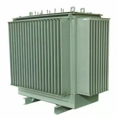
fuel tank
The body (winding and core) of an oil-immersed transformer is housed in a tank filled with transformer oil, which is welded with steel plates. The fuel tank of the small and medium-sized transformer is composed of a box shell and a box cover, and the body of the transformer is placed in the box shell, and the box cover can be lifted out of the body for pick-up and repair. Large and medium-sized transformers, due to the large and bulky body, the lifting body is inconvenient, and they are made into a box shell that can be lifted. This kind of box shell is a bell jar, when the body is to be overhauled, the lighter box shell, that is, the upper fuel tank, the body will be fully exposed.
The fuel tank of the large-capacity transformer is widely used in a fully enclosed structure, that is, between the main fuel tank and the top steel plate of the fuel tank or between the upper fuel tank and the lower fuel tank, it is welded to death, and the sealing gasket is not used to prevent the sealing from being unreliable. In order to facilitate maintenance, there is an entrance door or a hand hole door in the appropriate part.
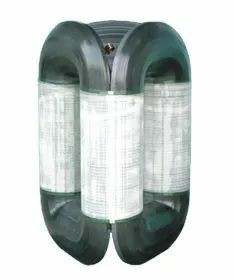
Oil pillow
The oil pillow, also known as the oil storage tank, is a kind of oil protection device, which is a barrel container made of mountain steel plate, which is horizontally installed on the transformer oil tank cover and connected with the oil tank with a bent pipe. One end of the oil pillow is equipped with an oil level gauge (oil mark tube), from which the oil level can be monitored for changes in oil level. The volume of the oil pillow is generally 8%~10% of the oil volume of the transformer oil tank.
When the volume of transformer oil expands or shrinks with the temperature of the oil, the oil pillow plays the role of oil storage and oil replenishment, so as to ensure that the oil tank is full of oil. At the same time, due to the installation of oil pillows, the contact surface between the transformer oil and the air is reduced, and the deterioration rate of the oil is reduced.
Sealed oil pillows are commonly used in large transformers, and there are the following two structures.
Diaphragm oil pillow
Diaphragm oil pillow uses a thin film (diaphragm) to isolate the oil from the atmosphere. The oil pillow is a horizontal cylinder, with a layer of film sandwiched between the flange of the middle plane, which separates the internal space of the oil pillow into two parts, the transformer oil below the film, and the air above the film. The material of the film is nylon cloth covered with nitrile butadiene rubber, which has very low air permeability and high oil resistance and low temperature adaptability (-43°C). The life of the film is normal after the oil temperature of 60°C drives the film 100,000 times. The oil tank of the oil pillow can withstand a full vacuum, so vacuum oil filling can still be achieved after the oil pillow is installed. The air side of the membrane is connected to a respirator to communicate with the atmosphere.
Capsule-type oil pillow
The capsule type oil pillow uses a synthetic rubber container in the upper space of the surface of the oil in the oil pillow, the rubber container is oil-free, and the rest of the space in the oil pillow is filled with transformer oil. The shape of the rubber container allows it to adapt to the change in oil level caused by the thermal expansion and contraction of the oil through its shape change. Since the rubber container is made of nitrile rubber with excellent oil resistance and weather resistance, and high mechanical strength, the device has sufficient reliability in long-term operation. Inside the rubber container, the air communicates with the outside air through a hygroscopic filtering respirator to prevent the container from deteriorating. And always maintain atmospheric pressure inside the rubber container. In addition, since the bottom of the rubber container is made to be level according to the amount of oil at the time, the bottom of the container is indicated as the oil level by the oil level gauge.
respiratory organ
Respirators, also known as dehydrating breathers, usually consist of a tube and glass container filled with desiccant (silica gel or activated alumina). When the air in the oil pillow expands or shrinks with the volume of the transformer oil, the air discharged or sucked passes through the respirator, and the desiccant in the respirator absorbs the moisture in the air and filters the air, so as to keep the oil clean. The silica gel soaked in chlorinated drills is blue when dry, but as the silica gel absorbs water and is close to saturation, the granular silica gel turns to pink white or red, according to which it can be judged whether the silica gel has failed. The damp silica gel can be regenerated by heating and drying, and when the color of the silica gel particles changes to cobalt blue, the regeneration work is completed.
Pressure relief device
Pressure relief devices play an important role in protecting power transformers. If there is an internal fault or short circuit in a power transformer filled with transformer oil, the arc discharge will vaporize the oil instantaneously, causing the pressure in the tank to rise extremely quickly. If this pressure is not relieved very quickly, the tank will burst, injecting flirtatious fuel into a large area, potentially causing fires and causing more damage, so measures must be taken to prevent this from happening. There are two types of pressure relief devices: explosion-proof pipes and pressure releasers, explosion-proof pipes are used for small transformers, and pressure releasers are used for large and medium-sized transformers.
Explosion Proof Pipe (also known as Fuel Injection Pipe)
The explosion-proof tube is installed on the top cover of the transformer, and the flared tube is connected to the oil pillow or atmosphere, and the nozzle is sealed by a film. When there is a fault inside the transformer, the oil temperature rises, and the oil decomposes violently to produce a large amount of gas, which makes the pressure in the oil tank increase sharply. When the pressure in the fuel tank rises to 50000Pa, the explosion-proof pipe film is broken, and the oil and gas are sprayed out from the nozzle, preventing the explosion or deformation of the transformer's oil tank.
Pressure reliever
Compared with explosion-proof pipes, pressure dischargers are widely used in large and medium-sized transformers because of their advantages of small opening pressure error, short delay time (only 2ms), high control temperature, and repeated action.
A pressure reducer, also known as a pressure reducer, is mounted on the top cover of a transformer tank, similar to a boiler safety valve. When the pressure in the fuel tank exceeds the specified value, the pressure release seal door (valve) is opened, the gas is discharged, and after the pressure is reduced, the seal door closes by itself by spring pressure. It can be removed before the pressure release is put into operation or during maintenance, and its operating pressure can be measured and corrected.
The adjustment of the operating pressure of the pressure reducer must be coordinated with the setting of the operating flow rate of the gas relay. If the operating pressure of the pressure reliever is too low, the pressure in the tank may be released too quickly, causing the gas relay to refuse and expanding the scope of transformer faults.
It utilizes an adjustable spring to press down on the valve disc (disc door), and when the pressure inside the tank is higher than the spring pressure, the valve cover is jacked up, i.e., the exhaust valve opens. Under normal conditions, the total thrust force of the pressure in the tank on the valve disc is the pressure on the total area of the sealing ring (smaller diameter) in the valve disc. Once the disc is seated (jacked), the total thrust acting on the disc is the pressure on the total volume of the outer sealing ring of the disc, and the disc seat force is greater. As a result, once the disc is seated, it can be fully opened within a few milliseconds.
When the valve disc is opened, the upper end of the action indicator is pushed out of the exposed hood and the ring of the indicator sleeve is used to hold it in the open position, and it is still clearly visible at a distance, indicating that it has acted. The indicator can only be reset manually by pushing it to land on the disc. After the pressure release is acted, its contact action, this contact can be connected in parallel with the gas relay trip contact, acting on the transformer tripping, so as to prevent the pressure release from releasing the pressure and making the gas relay refuse to move and not send a trip command.
The pressure release is installed on the upper part of the fuel tank cover, and a section of lifting pipe is generally connected to make the height of the release device equal to the height of the oil pillow, so as to eliminate the difference between oil pressure and static pressure under normal conditions.
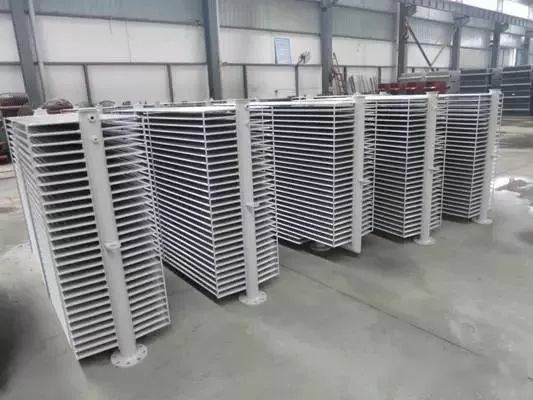
Radiator (also known as cooler, heat dissipation fin)
The radiator is in the form of corrugated, fan-shaped, round, row pipe, etc., and the larger the heat dissipation area, the better the heat dissipation effect. When there is a temperature difference between the upper oil temperature of the transformer and the lower oil temperature, the convection of the oil is formed through the radiator, and it flows back to the oil tank after cooling by the radiator, which plays a role in reducing the temperature of the transformer. In order to improve the cooling effect of the transformer, measures such as air cooling, forced air cooling and strong oil water cooling can be adopted.
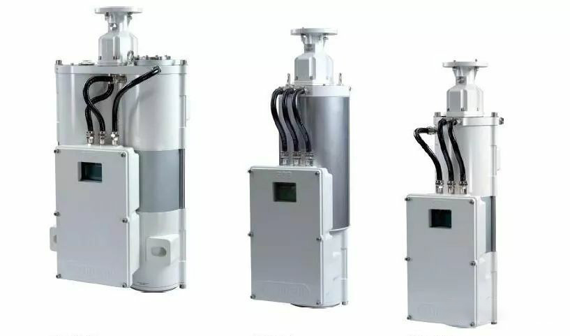
Insulating sleeves
When the lead-out wire of the transformer winding passes through the fuel tank from the inside of the box, it must pass through the insulating sleeve arm to insulate the live lead. The insulating sleeve is mainly composed of a central conductive rod and a porcelain sleeve. The conductive rod is connected to the winding at one end inside the tank, and with the outer wiring at the outer end.
The structure of the insulating sleeve depends mainly on the voltage level. For those with low voltage, a simple solid porcelain sleeve is generally used. When the voltage is high, in order to strengthen the insulation ability, there is an oil-filled layer between the porcelain sleeve and the conductive rod, which is called the oil-filled sleeve, and the voltage is above 110kV, and the capacitive oil-filled sleeve is used, which is referred to as the capacitive sleeve. In addition to filling the oil in the inner cavity of the porcelain sleeve, the capacitive sleeve is also wrapped with a capacitive insulator between the central conductive rod (hollow copper tube) and the flange to act as the main insulation between the flange and the conductive rod.
Tap-changers (a.k.a. switchers)
A tap-changer is a device that adjusts the transformer ratio. The primary winding of the double-winding transformer and the primary and secondary windings of the three-winding transformer generally have 3, 5, 7 or 19 separate positions. The middle split of the tap is the position of the rated voltage. The voltage difference between the adjacent splits of the 3 taps is 5%, and the voltage difference between the adjacent splits of the multiple splits is 2.5% or 1.25%. The operating part is installed on the top of the transformer, and the oil tank of the transformer is extended through the transmission rod. According to the needs of the operation of the system, the location of the tap is selected according to the indicated markings.
The voltage regulating device of the transformer is divided into two modes: no-load voltage regulation and on-load voltage regulation. The non-load tap-changer is switched without electricity, and its structure is single. The on-load tap-changer is switched without power failure, in order not to cause a short circuit between the two switching taps during the switching process, a transition circuit must be connected, usually using a resistor or reactance jumper between the two taps of the switcher as a transition. Therefore, the on-load tap-changer includes a transition circuit. The structure is more complex. However, its switching taps can be carried out under load, so it is widely used in power systems.
Gas Relays (also known as Gas Relays)
The gas relay is the main protection facility of the transformer, which can reflect various faults and abnormal operation conditions inside the transformer, such as oil level drop, insulation breakdown, moisture, heating or discharge faults of the core and winding, etc., and the function is sensitive and fast, the structure is simple, and the maintenance and repair are convenient.
The gas relay is installed on the connecting pipe between the transformer oil tank and the oil pillow, and the arrow direction on the relay should point to the oil pillow, and the installation slope of 1%~1.5% is required to ensure that the gas generated when the transformer is faulty can flow smoothly to the gas relay.
Gas relays are divided into two types: for transformer body protection and for on-load voltage regulation transformer box protection.
At present, QJ1-80 baffle gas relay is often used for transformer body protection. When there is a slight fault inside the transformer, the gas generated by the decomposition of the oil accumulates in the upper part of the relay, and when the total amount of gas reaches 250~300cm3, the light gas contact in the relay is connected to send an alarm signal. If the internal fault of the transformer is serious, there will be a strong oil and gas flow, and the inner baffle of the impulse relay will close the heavy gas contact, turn on the switch trip circuit, and cut off the power supply of the transformer.
QJ1-50 baffle gas relay is often used for on-load tap-changer gate box (additional fuel tank) protection. The gate box is not connected with the main oil tank, and is equipped with an on-load pressure regulating switch. If a gas relay has a pair of contacts, it acts directly on the trip. If there are two pairs of contacts, one pair of light and heavy gas is used, which acts on alarm and trip respectively.
The float gas relay manufacturing plant has ceased production.
In addition to baffle gas relays, some large power plants also have a type of gas relay called pitot tube type installed on the main transformer, which is different from the general gas relay in that it can prevent malfunction due to earthquakes. Its characteristic is that the reaction to the heavy gas action is the use of the "pitot tube" principle, that is, to measure the dynamic pressure and static pressure of the oil flow, the dynamic pressure and static pressure to both sides of a diaphragm box, when the pressure difference reaches the setting value, the diaphragm box deformation, drive the micro switch, send out a trip pulse. Therefore, it reacts to the flow rate and not to the vibration. The principle and structure of the light gas reaction part are the same as those of general gas relays.
Transformers installed in areas with seismic crack level 7 and above should be equipped with shockproof gas relays.

Oil purifier (also known as thermofilter)
An oil purifier is a container filled with an adsorbent (silica gel or activated alumina) that is installed on the sidewall of a transformer tank or in the lower part of a strong oil cooler. During the operation of the transformer, due to the temperature difference between the upper and lower oil layers, the transformer oil passes through the purifier from the top down to form convection. The oil is in contact with the adsorbent, and the moisture, acids and oxides in it are absorbed, making the oil clean and prolonging the service life of the oil. When silicone is used, its mass is 1% of the mass of transformer oil; When activated alumina is used, its mass is 0.5% of the mass of transformer oil.
insulation
The internal insulation of the transformer is divided into two parts: main insulation and longitudinal insulation. The main insulation refers to the insulation between the windings to the ground, between the phases and between the windings of the same phase and different voltage levels, and the main insulation mainly adopts the oil-separator insulation structure, which is usually formed by adding a covering layer, a clad insulation layer and an oil gap of the separator; Longitudinal insulation refers to the insulation between different parts of a winding of the same voltage level, such as layers, turns, windings and electrostatic screens.
Key words:
Aceite-transformador de poder lmmersado
Recommended

KAIBEITE Commissions Custom 3,000 kVA Transformers for Tanzanian Industrial Client


Phone/WhatsApp:
Email:
Address
Kaibeite Industrial Park, No. 121 Xiaozhai Town, Anyang, Henan Province, China
HUATAO GROUP
Leave Message
Expand your business with a trusted partner