
.jpg")
High and Low Voltage Switchgear HXGN-12
Categories:
High And Low Voltage Switchgears
Email:info@byttransformers.com
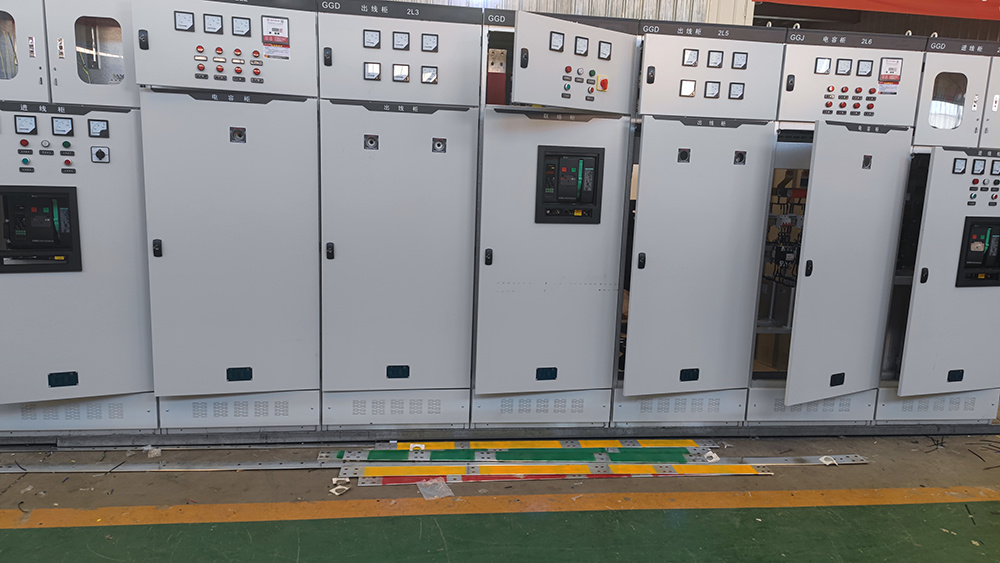
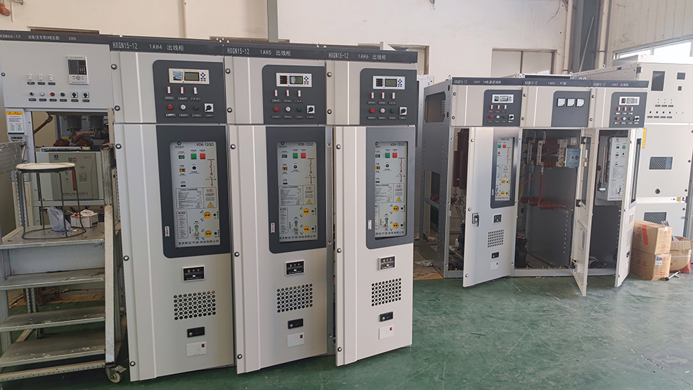
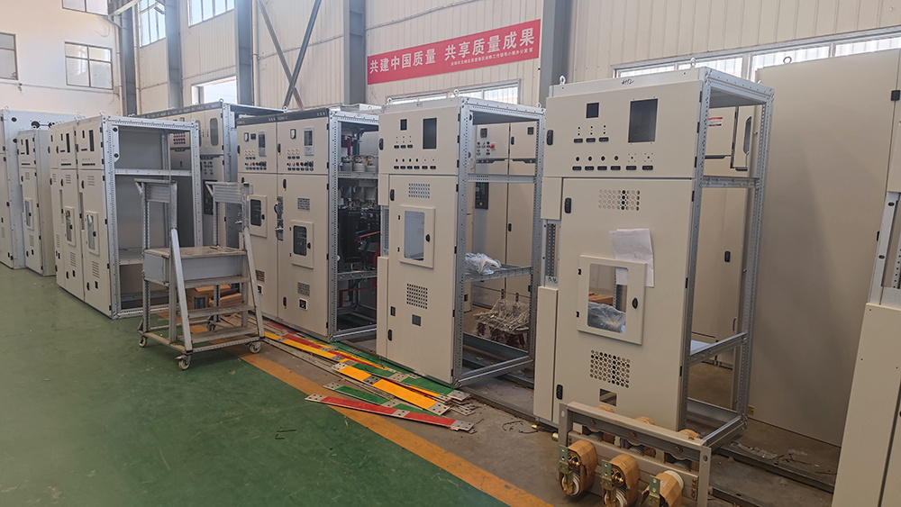
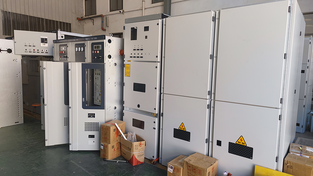
Product Pictures
Introduction of High and Low Voltage Switchgear HXGN-12
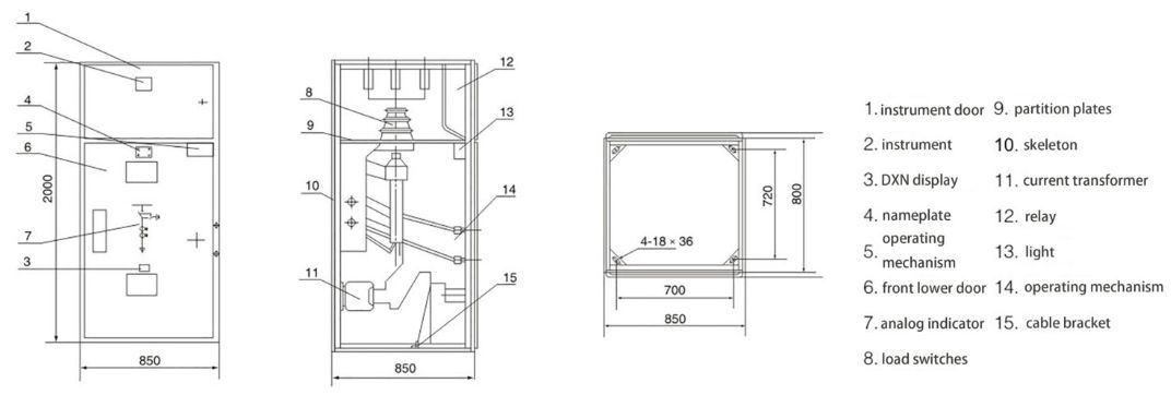
Some structural features of High and Low Voltage Switchgear HXGN-12:
The HXGN-12 High and Low Voltage Switchgear is constructed from 8MF type steel, which is partially welded and then bolted together. It primarily houses the FZN21-12 type two-position vacuum load switch, which is used in conjunction with a fuse equipped with an impactor to form a combined electrical device. This type of switchgear can be flexibly equipped with current transformers (CT), potential transformers (PT), and ZnO surge arresters. Its base is fitted with a removable access cover for easy cable entry, and for overhead cable entry, a busbar channel can be added according to user requirements.
High and low voltage switchgear systems are critical components in electrical power distribution networks, ensuring the safe and reliable operation of various electrical circuits. These switchgear units are designed to manage the flow of electrical energy by controlling, protecting, and isolating electrical equipment in both high and low voltage systems. Our high and low voltage switchgear provides an optimal solution for industrial, commercial, and utility applications, offering superior protection against electrical faults and overloads, and ensuring the continued operation of power distribution systems.
High voltage switchgear is primarily used in power generation, transmission systems, and substations, handling electrical voltages that exceed 1kV. It is engineered with cutting-edge technology to ensure maximum reliability and operational safety in environments with high electrical stress. These units typically feature circuit breakers, disconnectors, and protection relays that ensure seamless operation and swift response in case of faults. With their robust construction, high voltage switchgear systems are designed to perform under extreme conditions while minimizing downtime and operational disruptions.
Low voltage switchgear, on the other hand, is designed for power distribution systems within residential, commercial, and industrial facilities, operating at voltages below 1kV. It provides a vital role in controlling and distributing electricity across smaller electrical circuits, such as those found in buildings and manufacturing plants. Our low voltage switchgear incorporates advanced features, such as automated protection devices, fault detection systems, and real-time monitoring, to ensure reliable and efficient operation. Both high and low voltage switchgear systems are customizable to meet specific project requirements, offering enhanced flexibility, scalability, and future-proof performance.
| No. | Item | Unit | Data | |
|---|---|---|---|---|
| 1 | Rated Voltage | KV | 7.2/12 | |
| 2 | Main Busbar Rated Current | A | 400;630;1250 | |
| 3 | Rated Current | Incoming Cabinet | A | 400;630;1250 |
| Outlet Cabinet | A | 125 | ||
| 4 | Rated Short time Withstand Current | KA | 20 | |
| 5 | Rated Peak Withstand Current | KA | 31.5 | |
| 6 | Rated Short Circuit Closing Current Peak Value | KA | 50 | |
| 7 | Rated Active Load Breaking Current | A | 630 | |
| 8 | Rated Closed Loop Breaking Current | A | 630 | |
| 9 | Rated Cable Charging Current | A | 10 | |
| 10 | Ground Switch Rated Short Time Withstand Current | KA | 20 | |
| 11 | Ground Switch Rated Peak Withstand Current | KA | 50 | |
| 12 | Ground Switch Rated Short Circuit Closing Current Peak value | KA | 50 | |
| 13 | Rated AC Current of Combination Apparatus | A | 3150 | |
| 14 | 1min Power Frequency Withstand Voltage | Interphase Relative Vacuum Fracture | KV | 42 |
| Isolating Distance | 48 | |||
| 15 | Lightning Impulse Withstand Voltage | Interphase Relative Vacuum Fracture | KV | 75 |
| Isolating Distance | 85 | |||
| 16 | Mechanical Life | Vacuum Load Switch | time | 10000 |
| Isolation Knife Grounding Knife | 2000 | |||
| 17 | Load Switch | Average Closing Speed | m/S | 0.6±0.2 |
| Average Opening Speed | m/S | 1.1±0.2 | ||
| Three-phase Different Phases | mS | ≤2 | ||
| 18 | Fuse for Combined Appliances | Maximum Rated Current | A | 125 |
| Rated Short Circuit Breaking Current | KA | 31.5 | ||
| 19 | IP Code | IP2X | ||
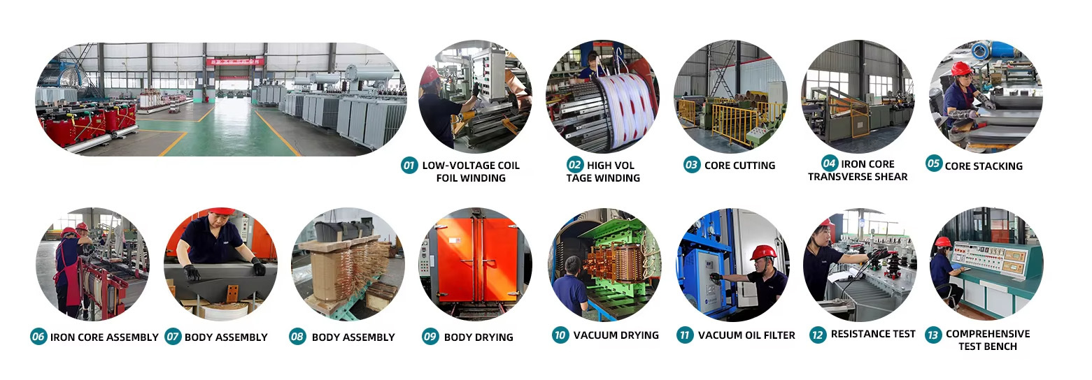
Production proces
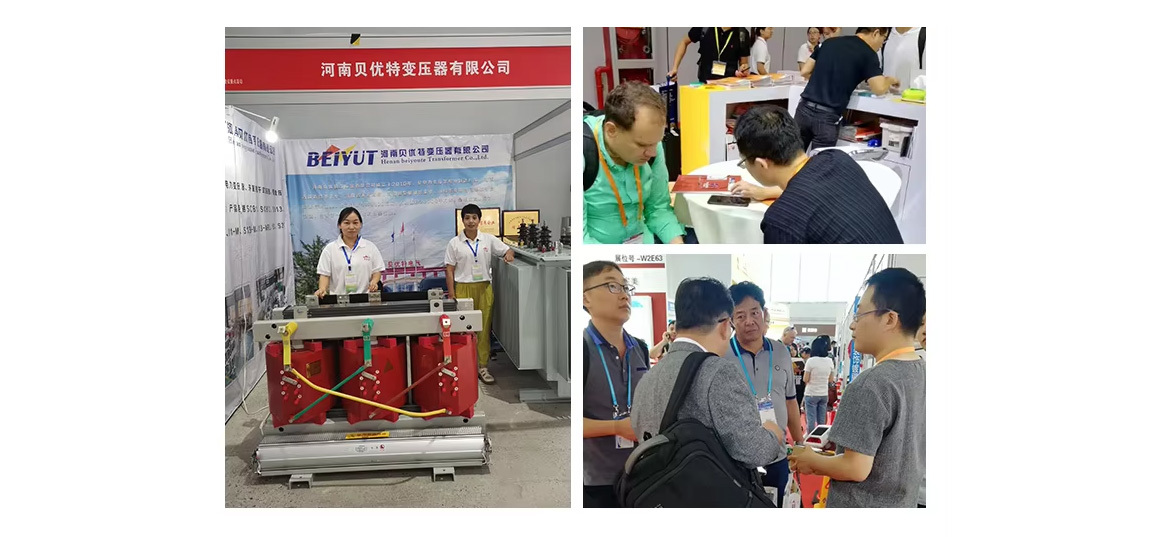
Customer Case

Cooperation Partners

Our Exhibition
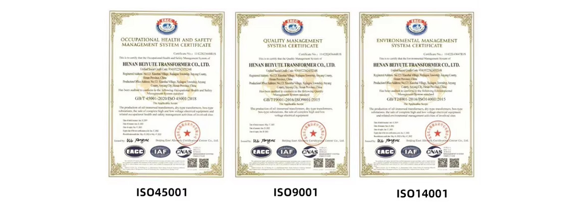
Our Certificates
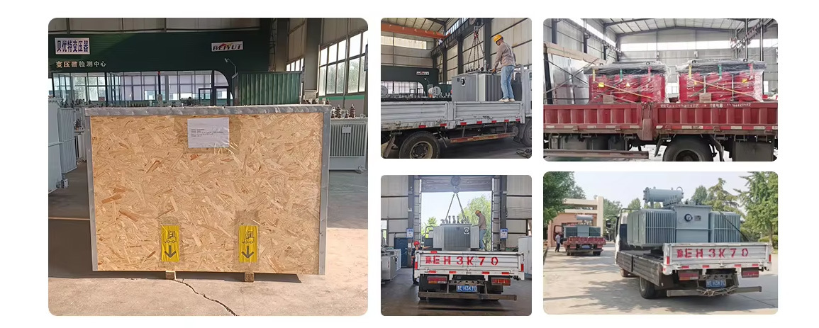
Payment & Delvery
FAQ