
Iron and copper losses in transformers
Any kind of electrical equipment in a long time operation will appear loss, power transformer is no exception. In the power transformer loss, mainly divided into copper loss and iron loss two parts.
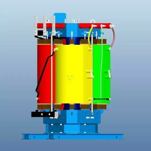
Copper loss
Definition and principle
Copper in the transformer plays an important role in the transformer winding will usually use copper wire, which transformer “copper loss” is the loss of copper wire. The “copper loss” of a transformer is also known as the load loss. The so-called load loss is the variable loss, which is changing. When the transformer is running under load, the current through the wire will have resistance, resulting in resistance loss. According to Joule's law, this resistance flows through the current will produce Joule heat, and the greater the current, the greater the power loss. As a result, the resistance loss is proportional to the square of the current, independent of the voltage. It is because it changes with the size of the current changes, so the copper loss (load loss) is variable loss, it is also the main loss in the operation of the transformer.

Influencing factors
Current size: as mentioned above, copper loss and the square of the current is proportional to the square, so the current size is the key factor affecting the copper loss.
Winding resistance: the size of the winding resistance directly affects the copper loss. The higher the resistance, the higher the copper loss. Coil layers: the more layers of coil, the longer the path of current flow in the winding, the resistance will increase accordingly, resulting in increased copper losses. Switching frequency: The effect of switching frequency on transformer copper loss is directly related to the distribution parameters and load characteristics of the transformer. In the load characteristics and distribution parameters together with the inductive characteristics, copper losses with the increase in switching frequency and reduce; together with the capacitive characteristics, copper losses with the increase in switching frequency and increase. Temperature effect: the load loss is also affected by the transformer temperature, while the leakage flux caused by the load current will produce eddy current loss in the winding, and the metal part of the winding outside the stray loss.
Calculation
There are two kinds of calculation formulas
1. Formula based on rated current and resistance:
Copper loss (unit: kW) = I² × Rc × Δt
Where I is the rated current of the transformer, Rc is the resistance of the copper wire, Δt is the operating time of the transformer.
2. Formula based on rated current and total copper resistance: copper loss = I² × R
Where I represents the rated current of the transformer and R represents the total copper resistance of the transformer. The total copper resistance R of the transformer can be calculated by the following formula:
R = (R1 + R2) / 2
Where, R1 denotes the primary side copper resistance of the transformer and R2 denotes the secondary side copper resistance of the transformer.
Methods of reducing copper losses
Improve the winding cross-sectional area of the transformer: reduce the conductor resistance, thus effectively reducing the transformer copper loss. Adopt high-quality conductor material: such as copper foil or aluminum foil to reduce the winding resistance. Reduce the light-load operation time of the transformer: limit the proportion of time for light-load operation of the transformer, which is conducive to reducing the copper loss of the transformer.
Iron loss
Definition and principle
Different from copper loss, iron loss of transformer has nothing to do with the winding, current size and other factors, as the name suggests, iron loss is related to iron, it is generated by the iron core. Transformer iron loss is also known as “no-load loss”, because it exists in the transformer full load, zero load state, is a kind of fixed transformer loss. However, in a load, the power loss decreases as the electric field strength decreases.
Classification
The iron loss of a transformer is subdivided into hysteresis loss and eddy current loss.
Hysteresis losses are based on the principle of electromagnetic induction to realize the rise and fall of voltage and change of current, and the magnetic flux inside the transformer flows in the iron core, which has a magnetic resistance to the magnetic flux, just as a conductor has a resistance to the electric current, and generates heat, which is known as “hysteresis loss.
Eddy current loss when the primary winding of the transformer is energized, the magnetic flux generated by the coil in the core flow, because the core itself is a conductor, perpendicular to the plane of the magnetic lines of force will be induced potential, this potential in the cross-section of the core to form a closed loop and generate current, like a vortex, so it is known as “eddy current”. The loss generated by this eddy current is called “eddy current loss”. It is precisely because the core generates eddy currents that it is made into a thin piece, because the thinner it is, the higher the resistance and the lower the current.
Classification
The iron loss of transformer is divided into hysteresis loss and eddy current loss.
Hysteresis loss The working principle of transformer is based on the principle of electromagnetic induction to realize the rise and fall of voltage and change of current, and the magnetic flux inside the transformer flows in the iron core, which is magnetically resistive to the magnetic flux, just as a conductor is resistive to the electric current, and generates heat, and such loss is called “hysteresis loss”.
Eddy current loss when the primary winding of the transformer is energized, the magnetic flux generated by the coil in the core flow, because the core itself is a conductor, perpendicular to the plane of the magnetic lines of force will be induced potential, this potential in the cross-section of the core to form a closed loop and generate current, like a vortex, so it is known as “eddy current”. The loss generated by this eddy current is called “eddy current loss”. It is precisely because the core generates eddy currents that it is made into a thin piece, because the thinner it is, the higher the resistance and the lower the current.

Influencing factors
Operating voltage and frequency: iron loss and transformer operating voltage and frequency, because these factors will affect the magnetic field strength and hysteresis phenomenon in the core. Iron core material: the hysteresis nature of the core material will affect the size of the iron loss. If the core material is not well selected, the hysteresis loss will increase. Manufacturing process: the manufacturing process of the transformer also has a certain impact on the iron loss. For example, the core stacking method, insulation treatment, etc. will affect the size of the iron loss.
Calculation
1. Based on the rated current and hysteresis, resistance loss formula:
Iron loss (unit: kVA) = I² × (Rm + Ra)
Where I is the rated current of the transformer, Rm is the hysteresis loss of the core, Ra is the resistance loss of the core.
2. Equation based on constant, flux density and operating frequency:
P iron = Kf × (Bm)^2 × f
Where PFe is the iron loss, Kf is the constant, Bm is the magnetic flux density, and f is the transformer operating frequency.
Reduction method
Selection of high-quality core materials: selection of hysteresis loss of small core materials, can reduce the iron loss of the transformer.
Optimize the manufacturing process: by improving the iron core stacking method, insulation treatment and other manufacturing processes, reduce iron loss.
Reasonable design: in the design stage of the transformer, through the optimization of structural design and parameter selection, reduce iron loss.
Key words:
Aceite-transformador de poder lmmersado
Recommended

Repeat Order: 15 Oil-Immersed Transformers Ready for Cameroon


Phone/WhatsApp:
Email:
Address
Kaibeite Industrial Park, No. 121 Xiaozhai Town, Anyang, Henan Province, China
HUATAO GROUP
Leave Message
Expand your business with a trusted partner