
Transformer main protection and backup protection knowledge

A transformer is a stationary device that operates continuously and operates more reliably with fewer chances of failure. However, due to the fact that most of the transformers are installed outdoors and are affected by the load during operation and the impact of short-circuit faults in the power system, various faults and abnormal situations inevitably occur during operation.
1. Common faults and abnormal
faults of transformers can be divided into internal faults and external faults.
Internal faults refer to the faults that occur inside the casing, including the phase-to-phase short-circuit fault of the winding, the turn-to-turn short-circuit fault of the one-phase winding, the short-circuit fault between the winding and the iron core, and the disconnection fault of the winding.
External faults refer to various interphase short-circuit faults between the external lead wires of the transformer, and single-phase grounding faults that occur when the insulating sleeve of the lead wire flashover passes through the box shell.
Transformer failure is very harmful. Especially in the event of an internal fault, the high-temperature arc generated by the short-circuit current will not only burn out the insulation and core of the transformer winding, but also cause the transformer oil to be heated and decomposed to produce a large amount of gas, causing the deformation and even explosion of the transformer shell. Therefore, when a transformer fails, it must be removed.
The abnormalities of the transformer mainly include overload, oil level reduction, overcurrent caused by external short circuit, high oil temperature of the transformer in operation, high winding temperature, high pressure of the transformer, and failure of the cooling system. When the transformer is in an abnormal operating state, an alarm signal should be given. 2. The main protection of short-circuit fault is configured
for transformer protection: mainly longitudinal protection, heavy gas protection, etc.
Backup protection for short-circuit faults: mainly includes composite voltage lock-out over-current protection, zero-sequence (direction) over-current protection, low-impedance protection, etc.
Abnormal operation protection: mainly overload protection, over-excitation protection, light gas protection, neutral point gap protection, temperature and oil level and cooling system fault protection, etc.
3. Non-electric protection
: transformer protection composed of non-electrical quantities such as oil, gas, and temperature of the transformer is called non-electric protection. There are mainly gas protection, pressure protection, temperature protection, oil level protection and cooler total stop protection. The non-electric protection acts on tripping or signaling according to the needs of the site.
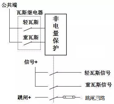
(1) Gas protection
When the inside of the transformer fails, due to the effect of short-circuit current and short-circuit point arc, a large amount of gas will be generated inside the transformer, and the oil flow speed of the transformer is accelerated, and the protection realized by using gas and oil flow is called gas protection.
Light gas protection: When a slight fault or abnormality occurs inside the transformer, the fault point is partially overheated, causing part of the oil to expand, and the gas in the oil forms bubbles into the gas relay, and the light gas protection action sends out a light gas signal.
Heavy gas protection: When a serious fault occurs in the transformer oil tank, the fault current is large, the arc makes a large amount of transformer oil decompose, generating a large amount of gas and oil flow, and the impact baffle makes the heavy gas follow the protection action, send out a heavy gas signal and trip the outlet, and cut off the transformer.
Heavy gas protection is the main protection for internal faults in the fuel tank, which can reflect various faults inside the transformer. When a small number of turn-to-turn short circuits occur in the transformer, although the fault current is large, the differential current generated in the differential protection may not be large, and the differential protection may be rejected. Therefore, for the internal fault of the transformer, it is necessary to rely on heavy gas protection to remove the fault.
(2) Pressure protection
: Pressure protection is also the main protection for internal faults in the transformer tank. Contains pressure release and pressure mutation protection, and is used to reflect the pressure of transformer oil.
(3) Temperature and oil level protectionWhen
the temperature of the transformer rises to the early warning value, the temperature protection sends an alarm signal and puts in the starting standby cooler. When the transformer leaks oil or the oil level decreases due to other reasons, the oil level protection action sends an alarm signal.
(4) Cooler full stop protectionWhen
the transformer cooler in operation is fully stopped, the transformer temperature will rise, and if it is not dealt with in time, it may cause damage to the transformer winding insulation. Therefore, when the cooler is completely stopped during the operation of the transformer, the protection sends an alarm signal and removes the transformer after a long delay.
4. Differential protection
transformer differential protection is the main protection of transformer electrical quantity, and its protection range is the part surrounded by the current transformer on each side. In the event of a fault such as a phase-to-phase short circuit or an inter-turn short circuit in the windings that occurs in this range, the differential protection must be activated.
(1) The excitation inrush current
of the transformer is called the excitation inrush current generated when the transformer is airdropped. The magnitude of the excitation inrush current is related to the structure of the transformer, the closing angle, the capacity, the remanence before closing, and other factors. The measurement shows that due to the large saturation excitation inrush current of the iron core, the airdrop transformer is usually 2~6 times of the rated current, and the maximum can reach more than 8 times. Since the excitation inrush current flows into the transformer only on the charging side, a large differential current is generated in the differential circuit, resulting in differential protection malfunction.
The excitation inrush current has the following characteristics: a. The inrush current value is very large and contains obvious aperiodic components; b. The waveform is spire-shaped and intermittent; c. It contains obvious higher harmonic components, especially the second harmonic components are the most obvious; d. The excitation inrush current is attenuated.
According to the above characteristics of the excitation inrush current, in order to prevent the differential protection malfunction of the transformer caused by the excitation inrush current, the three principles of high second harmonic content, waveform asymmetry and large waveform discontinuity angle are used in the project to realize the locking of differential protection.
(2) The essence of the second harmonic braking principle
is to use the second harmonic components in the differential current to determine whether the differential current is a fault current or an excitation inrush current. When the percentage of the second harmonic component and the fundamental component is greater than a certain value (usually 20%), it is judged that the differential current is caused by the excitation inrush current, and the differential protection is locked.
Therefore, the larger the second harmonic braking ratio, the more second harmonic currents are allowed in the fundamental wave, and the worse the braking effect will be.
(3) Differential quick-break protection
When there is a serious fault inside the transformer, and the fault current is large and the CT is saturated, the CT secondary current also contains a large number of harmonic components, according to the above description, it is likely that the differential protection will be locked or delayed due to the second harmonic braking. This will cause serious damage to the transformer. To solve this problem, differential quick break protection is usually set.
The differential quick-break element is actually a high-value differential element for longitudinal protection. Unlike a general differential element, it reflects the RMS value of the differential current. Regardless of the waveform of the differential current and the magnitude of the harmonic components involved, as long as the effective value of the differential current exceeds the setting value of the differential quick break (usually higher than the setting value of differential protection), it will immediately remove the transformer without locking through the criteria such as excitation inrush current.
A brief introduction to the main protection of the transformer, and the continuation of the backup protection of the transformer. There are many types of backup protection configurations of transformers, and here we mainly briefly introduce the two types of backup protection of transformers: revoltage locking overcurrent protection and grounding protection.
1. Overcurrent protection
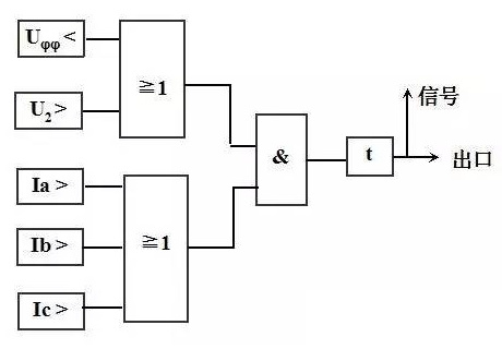
of re-voltage lock-out, over-current protection of re-voltage lock-out is the backup protection of interphase short-circuit faults of large and medium-sized transformers. It is suitable for step-up transformers, system contact transformers and step-down transformers whose over-current protection cannot meet the sensitivity requirements. The composite voltage composed of negative sequence voltage and low voltage can reflect various faults within the protection range, reduce the setting value of overcurrent protection, and improve sensitivity.
Composite voltage overcurrent protection is composed of composite voltage element, overcurrent element, and time element. The protected access current is the CT secondary three-phase current on the transformer side, and the access voltage is the PT secondary three-phase voltage on the transformer side or other sides. For microcomputer protection, the voltage of this side can be provided to other sides through software, so as to ensure that the overvoltage and overcurrent protection can still be used when any PT on one side is overhauled. The action logic is shown in the following figure.
2. The grounding protection
of the transformer The backup protection of the grounding short-circuit fault of the large and medium-sized transformer usually includes: zero sequence overcurrent protection, zero sequence overvoltage protection, gap protection, etc., and the following is briefly introduced according to three different grounding methods of the neutral point.
(1) For transformers with a neutral direct grounding
voltage of 110kV or above and a neutral direct grounding voltage, a zero-sequence current protection that reacts to the grounding fault should be set on the side of the high-current grounding system. For transformers that are directly grounded on both high and middle sides, the zero sequence current protection should be directional, and the direction should be directed to the bus on each side.
The principle of zero-sequence current protection is similar to that of zero-sequence protection of lines, and can be found in Issue 30. The zero sequence current can be taken from the neutral CT secondary current, or it can be self-generated by the local side CT secondary three-phase current. The zero-sequence voltage connected to the direction element can be taken from the PT open triangle voltage on the local side, or it can be self-generated by the secondary three-phase voltage on the local side. In the microcomputer protection device, the main way is self-produced.
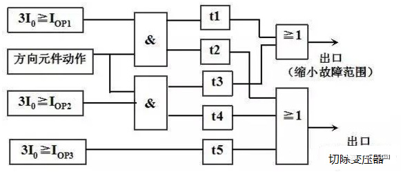
For large three-winding transformers, the zero-sequence current protection can be used in a three-stage type. Segment I and Segment II have direction, and Segment III has no direction. Each section generally has a two-stage delay, which reduces the fault range with a shorter delay (skipping bus connection or strip-side switch), and cuts off the transformer with a longer delay (skipping three-side switch). The specific protection configuration is determined based on the actual situation.
As shown in the figure, after the operation of the first or second section of the zero sequence direction current protection, the transformer is first cut off by a shorter delay t1 or t3 bus hop or skip local side switch to reduce the scope of fault influence, if the fault amount is still there, the transformer is cut off by the three-side switch with a longer delay t2 or t4 jump. The third stage has no direction and directly cuts off the transformer through a delay.
(2) The neutral point is not grounded, and the
zero sequence current passes through the neutral point of the transformer to form a zero sequence loop. However, if all transformer neutrals are grounded, the short-circuit current at the grounding point is shunted to the individual transformers, resulting in a reduction in the sensitivity of zero-sequence overcurrent protection. Therefore, in order to limit the zero sequence current to a certain range, the number of transformers operating at the neutral point to ground is regulated.
For transformers that operate without grounding, in order to prevent overvoltage damage to the transformer caused by gap arcing at the fault point when the ground fault occurs, zero sequence voltage protection should be configured.
Due to the high level of insulation at its neutral point, when the system has a grounding fault, there is a zero-sequence current protection to cut off the transformer grounded at the neutral point, and if the fault still exists, there is a zero-sequence voltage protection to cut off the transformer that is not grounded at the neutral point.
(3) The neutral point grounding
ultra-high voltage transformers through the discharge gap are semi-insulated transformers, and the ground insulation of the neutral point coil is weaker than that of other parts. Neutral point insulation is susceptible to breakdown. Therefore, it is necessary to configure gap protection.
The function of gap protection is to protect the insulation safety of the neutral point of the neutral point of the transformer.
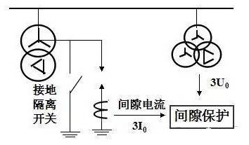
As shown in the figure, install a breakdown gap between the neutral point of the transformer and the ground. When the grounding isolation switch is closed, the transformer is directly grounded, and the zero-sequence overcurrent protection is put into use. When the grounding disconnector is disconnected, the transformer is grounded through the gap and put into the gap protection.
Gap protection is achieved by using the gap current 3I0 flowing through the neutral point of the transformer and the delta voltage 3U0 of the bus PT opening as a criterion.
If the neutral point of the fault is elevated, the gap breaks down, and a large gap current of 3I0 is generated, and the gap protection action is at this time, and the transformer is cut off by delay. In addition, when a grounding fault occurs in the system, the neutral point grounding runs the transformer zero sequence protection action, and the transformer grounded at the neutral point is cut off first. After the system loses the grounding point, if the fault still exists, the opening triangle voltage of the bus PT 3U0 will be very large, and the gap protection will also work. The protection logic is shown in the following figure.

Key words:
Aceite-transformador de poder lmmersado
Recommended

KAIBEITE Commissions Custom 3,000 kVA Transformers for Tanzanian Industrial Client


Phone/WhatsApp:
Email:
Address
Kaibeite Industrial Park, No. 121 Xiaozhai Town, Anyang, Henan Province, China
HUATAO GROUP
Leave Message
Expand your business with a trusted partner